More Extruding and Lofting
- Lesson 3-1INTRODUCTION TO 3-D (Terminology)
- Lesson 3-2ISOMETRIC DRAWING IN AUTOCAD
- Lesson 3-3WORKING IN 3 DIMENSIONS (X,Y,Z Axes, 3D Rotation)
- Lesson 3-4VIEWING 3-D OBJECTS (Perspective Views, 3D Orbit, DView)
- Lesson 3-5BASIC WIREFRAME MODELS
- Lesson 3-6LINE THICKNESS
- Lesson 3-7REGIONS AND 3-D FACES AND EXTRUDING
- Lesson 3-7aMORE ABOUT EXTRUDING & LOFTING
- Lesson 3-8REVOLVED OBJECTS - REVSURF AND REVOLVE
- Lesson 3-9ADDING MATERIALS IN AUTOCAD
- Lesson 3-10PRIMITIVE SOLIDS
- Lesson 3-11BOOLEAN OPERATIONS AND 3D EDITING
- Lesson 3-12CHANGING FROM THE WCS TO THE UCS
- Lesson 3-13MAPPING MATERIALS
- Lesson 3-14CREATING NEW MATERIALS
- Lesson 3-15EXTRA PROJECTS AND A TUTORIAL
- Lesson 3-16PUTTING IT ALL TOGETHER - MODEL A BUILDING
- Lesson 3-17INTRODUCTION TO RENDERING AND LIGHTING IN AUTOCAD
- Lesson 3-18CREATING ANIMATIONS IN AUTOCAD
- QUIZ FOR LEVEL 3 - 84 QUESTIONS
Topics covered in this Lesson:
Extruding | Lofting
The purpose of this lesson is to look further at the EXTRUDE command. As you saw in Lesson 3-7, it can be used to create a 3D solid from a closed 2D shape. Two other ways you can extrude (which you may have seen as options on the command line) are to taper the extrusion and the extrude a shape along a path. If you need to, you can also combine the two options and extrude along a path while tapering the shape (shown below).
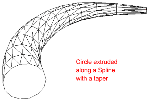
One example where you can use extruded paths is to represent pipes in a drawing. You may not use the tapered path option often, but at least you know it's there.
EXTRUDING ALONG A PATH
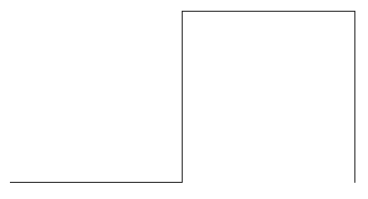
Draw a POLYLINE from 0,0 to 120,0 to 120,120 to 240,120 to 240,0 and then press <Enter> to finish the command.
Do a Zoom > Extents to see the polyline and then zoom out a little more. Your line should look like this:
Next you will put a 24 unit radius on all the corners. The easiest way to do this is using the Polyline option of the FILLET command.
Command: FILLET <ENTER>
Current settings: Mode = TRIM, Radius = 0.0000
Select first object or [Polyline/Radius/Trim/mUltiple]: R
Specify fillet radius <0.0000>: 24
Select first object or [Polyline/Radius/Trim/mUltiple]: P
Select 2D polyline: <SELECT THE POLYLINE>
3 lines were filleted
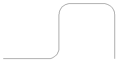
What you're going to do next is extrude a circle a long the polyline - or to be more accurate, the path of the polyline. This would be one way of drawing pipes in 3D. For this example, you'll draw a pipeline with a diameter of 12 units.
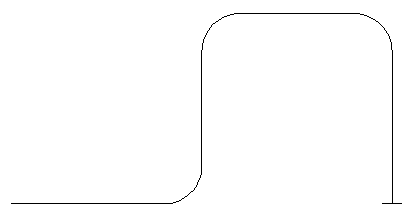
Next draw CIRCLE at the bottom right end of polyline. Use a diameter of 12 (radius of 6). Once you have that, you need to rotate it in 3D. This is covered in the next lesson as well. To do this, you will select the circle, select the axis you want it rotated around and then choose the angle.
Command: ROTATE3D
Current positive angle: ANGDIR=counterclockwise ANGBASE=0
Select objects: <SELECT THE CIRCLE> 1 found
Select objects: <ENTER>
Specify first point on axis or define axis by
[Object/Last/View/Xaxis/Yaxis/Zaxis/2points]: X Specify a point on the X axis
<0,0,0>: <SELECT THE BOTTOM RIGHT END OF THE POLYLINE - Make sure your Osnaps are on for endpoints>
Specify rotation angle or [Reference]: 90 <ENTER>
Your circle should have rotated 90 degrees and now you are looking at the side of it so the circle appears to be a line as shown in the image below.
Now comes the easy part. Next you will EXTRUDE the circle along the path of the polyline.
Command: EXT
EXTRUDE
Current wire frame density: ISOLINES=4
Select objects: <SELECT THE CIRCLE> 1 found
Select objects: <ENTER>
Specify height of extrusion or [Path]: P
Select extrusion path or [Taper angle]: <SELECT THE PLINE>
Note: After the Extrude command, the polyline will still be there. If you need to keep your drawing clean, remember to erase the path if you don't need it any more. To see how it looks, view the object in the SW Isometric view, and use the HIDE command. It should look like this:
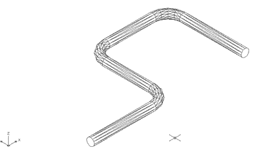
This is just one option available with the Extrude command. Try it on other paths and see how it works. You will find that if your circle is too large, it may not be able to be extruded on polylines with tight corners. You might then see this error on the command line: Unable to extrude the selected object.
Any object that can be extruded can be extruded along a path. A path can be any open object such as lines, arc, polylines, splines, etc.
For more practice, try to create a cord for your lamp (Lesson 3-8) using a Spline as the path. You can also extrude 2 circles along a path (make one one circle smaller) and then SUBTRACT the smaller diameter extrusion from the larger to create a hollow pipe.
EXTRUDING WITH A TAPER
Extruding along a taper gives you another option in your 3D toolbox. Here is an example of how it is done:
Draw a RECTANGLE 100 units by 100 units.
EXTRUDE the Rectangle 50 units high with a taper angle of 45 °. Here are the commands needed.
Command: EXT EXTRUDE
Current wire frame density: ISOLINES=4
Select objects to extrude: <SELECT THE RECTANGLE>
1 found
Select objects to extrude: <ENTER>
Specify height of extrusion or [Direction/Path/Taper angle] <1.0000>: T
Specify angle of taper for extrusion <0>: 45
Specify height of extrusion or [Direction/Path/Taper angle] <1.0000>: 50
Here is what you should have (a pyramid):
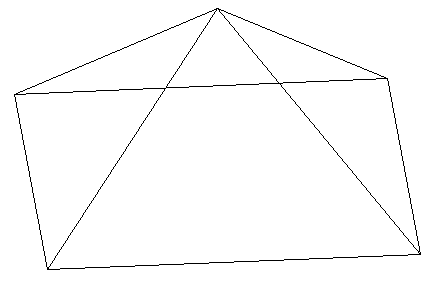
Use the 3DORBIT command to view it at different angles (Click on the screen, hold the button down and move the cursor around the screen). Try extruding different shapes with various taper angles for more practice.
These options give you a lot of versatility within one command. You may not use these options very often in your everyday drafting, but they're good to know.
LOFT COMMAND
New in AutoCAD 2007 (and long overdue) is the LOFT command. The loft command is similar to the extrude command, but much more versatile. Instead of extruding a single shape, the loft command allows you to extrude several shapes and make one continuous object.
Here's an example of how it works, I have drawn several shapes and aligned them with the same center. Next, they were copied above and below the largest circle. The goal is to create a smooth object from the 7 profiles shown below.
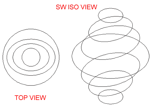
Here is a front view of the objects before and after the loft command:
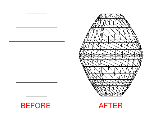
The example above is very simple, but think of how you can create complex shapes using this simple command.
USING THE LOFT COMMAND
The goal of this exercise is to create a "twisted Cube" - a 20x20x20 cube that looks like the top was twisted 45o. We're going to start with a simple step. Draw a square 20x20. Copy it in the same place. Rotated the 2nd square 45o using the midpoints of the square as the base point. Finally, move the 2nd square up 20 units. You should have something like this from the SW view:
From left to right, the original square, the copied and rotated square and the moved 2nd square. Copy the 2 rectangles over (out of the way) to use in another exercise.
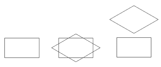
Next you will create a lofted object from the 2 rectangles using the defaults.
Command: LOFT
Current wire frame density: ISOLINES=4, Closed profiles creation mode = Solid
Select cross sections in lofting order or [POint/Join multiple edges/MOde]: <PICK BOTTOM SQUARE> 1 found
Select cross sections in lofting order or [POint/Join multiple edges/MOde]: <PICK TOP SQUARE> 1 found, 2 total
Select cross sections in lofting order or [POint/Join multiple edges/MOde]: Specify opposite corner: <ENTER> 0 found
Select cross sections in lofting order or [POint/Join multiple edges/MOde]: <ENTER>
2 cross sections selected
Enter an option [Guides/Path/Cross sections only/Settings] <Cross sections only>: <ENTER>
After the command, your two squares will be turned into one lofted 3D Solid.
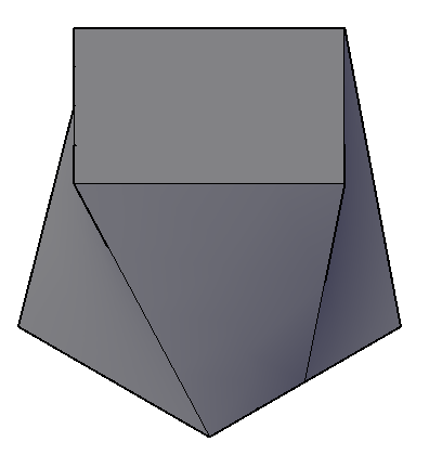
Now something doesn't look quite right to me. I would expect that corners of the squares would be even so that the lofted square looks like a 'twisted cube'. Instead, you can see lines going from the middle of the bottom square to a corner of the top square. Use the HIDE command to see how it looks. It looks a little strange, but you can make out that it has some odd shapes.
Take the pair of squares that you copied over earlier and draw lines from lower corner to upper corner as shown in the drawing below:
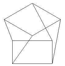
Now start the LOFT command again. This time you'll try something different. Select the squares again as your cross sections, then instead of accepting the default, use the Guides option G. Now select the four lines which will guide the loft to create a shape that better represents what you want.
Command: LOFT
Select cross-sections in lofting order: <SELECT SQUARE> 1 foundSelect cross-sections in lofting order: <SELECT OTHER SQUARE> 1 found, 2 total
Select cross-sections in lofting order: <ENTER
Enter an option [Guides/Path/Cross-sections only] <Cross-sections only>: G
Select guide curves: <SELECT LINE> 1 foundSelect guide curves: <SELECT LINE> 1 found, 2 total
Select guide curves: <SELECT LINE> 1 found, 3 total
Select guide curves: <SELECT LINE> 1 found, 4 total
Select guide curves: <ENTER>
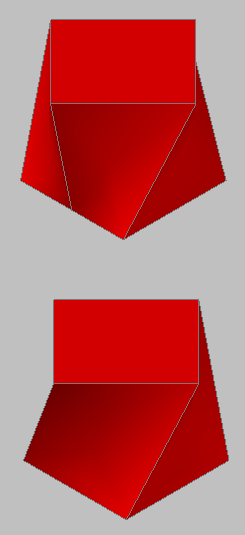
Compare the 2 objects, the 2nd one should look more like the goal of a twisted cube.
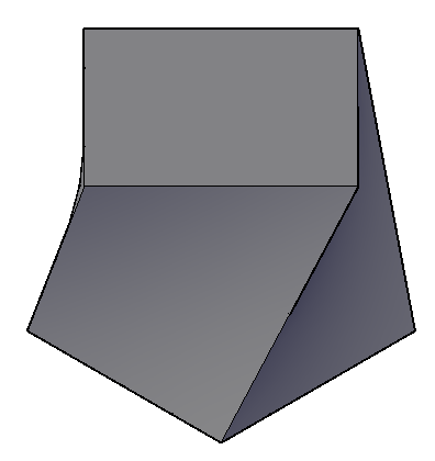
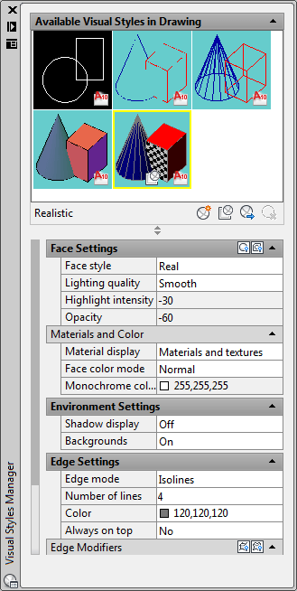
To change how you view things, use the VISUALSTYLES command to open the Visual Styles Manager palette. This command allows you to quickly change settings for how you view 3D objects that previously needed the knowledge of several system variables.
Use the settings highlighted below and press the "Apply to Current Viewport" button (or double click on any of the colored squares at the top. You should now have a clear view that illustrated the differences between the first lofted object and the second one that used guides.
Try creating your own lofted 3D Solids. Anything that can be extruded can be lofted - so any closed shape will work. Try lofting a rectangle to a circle. Try exploding a lofted object. There are many other options to this command, but in a effort to be brief and cover the basics, I will not go further into this command. (To explore further, select the Settings option in the command.) Remember to pick the cross sections in the correct order, add guides to better define the shape.
In review, you can see how extruding and lofting are two simple commands that give you a lot of power in the 3D world. Get familiar with extruding, as it is a great way to build things in 3D. Lofting will allow you to create more 'organic' shapes that previous versions of AutoCAD. Think of how you could use cross sections of a ship's hull to create a 3D model.
Extra Practice: Draw this object. Start with a 3DPolyline (3DPOLY) and then extrude the circle along the path of the polyline.
Extra Practice: Copy this drawing that shows the dimensions on the left and an isometric view for reference. Then create a lofted object (using the default setting) to look like this.
Experiment: What happens when you extrude a line along a line? Try this and use the LIST command see what type of object is created.
Video: Extrude (Path & Taper) - Loft Command
You Scored:

Fun fact: The annual revenue for Autodesk 2019 was $2.57B, ($2,570,000,000) a 24.95% increase from 2018.
Please support
MyCADsite.com
Give a donation!
Donate

- To cover this months server costs
- Exceeding amounts will go to creating new content
- Even a penny will help
Did you like the lesson? ❤️
